The GM Performance Build Center, located in Wixom, Michigan, is nestled in a nondescript industrial building at the end of a cul-de-sac. The sole purpose of the “PBC” is to produce General Motors’ most powerful factory built small block engines – including the vaunted LS9. In this article, LSX Magazine is going to take you – our reader – through an exclusive tour of the build of the ZR1’s monster powerplant. Read on.

Most GM Powertrain plants are staffed by hundreds of technicians, working on a moving assembly line, producing a large volume of one type of engine. The PBC isn’t like most GM Powertrain plants.
The Performance Build Center
The PBC is at the opposite end of mass production. With a small group of master engine builders, the PBC combines computer-aided assembly technology with race engine building principles. The end result is an LS7 and LS9 small block that puts out 505 and 638 horsepower respectively, with a 100,000 mile powertrain warranty. “We focus on that 1% of GM’s customer base,” said Jeff Stafford, PBC Area Manager. “The ZO6 and ZR1 Corvette is an image type of product, or halo car. The product we produce and its content is perceived to be unchallenged by the competition, and we think the LS7 and LS9 accomplish GM’s goals.”

The PBC idea was driven by Bob Lutz, who came on board at GM in 2001. Management saw the need to change GM Powertrain’s image through marketing, and the PBC’s customer focus is a great story to tell. Since its inception, any new Corvette owner can schedule a visit to tour the PBC, and Corvette events are held throughout the year at the facility. “The products we produce needed to be aspirational,” said Stafford. “We want to get those people that never thought of GM to give us a look and come on board with the ZO6 or ZR1.”
Opened in 2005 in a 100,000 square foot facility, the PBC’s first assignment was to build the 427ci LS7 for the C6 ZO6 Corvette. After the success of that program, it was tasked with assembling the supercharged DOHC LSA engine, found in the STS-V and XLR-V Cadillac. In 2008, when the long rumored “Blue Devil” Corvette program got the green light, the PBC was the natural selection for the ZR1’s LS9 build. “We benchmarked against the best engine build facilities in the industry,” recalled Stafford. “Mercedes’ AMG facility in Stuttgart was visited, and we looked at how they built their engines and their processes. We also looked at Hendrick Motorsports and how they did their NASCAR engine program.”

LSX Magazine got the opportunity to tour this impressive facility, and having built a few small block Chevy’s in our own garage, we were excited to get the chance to follow the build of the baddest-of-the-bad high performance engine from GM. Special thanks goes out to GM Powertrain’s Tom Read, PBC Area Manager Jeff Stafford, and the entire staff of the PBC, for allowing us to document the creation of an LS9 powerplant from bare block to complete running engine. Rick Dadd was the master engine builder assigned to our story, and he did a great job of explaining all the build steps while assembling all of the unique parts in the LS9 engine.
We came away from the tour with an appreciation for what GM Powertrain has accomplished by creating the Performance Build Center, and we saw how they are taking lessons learned with the “world beater” ZR1 Powertrain and applying it to the rest of the GM Powertrain lineup.
First, Let’s Take a Look at the LS9

The LS9 6.2L (376 cubic inch) supercharged engine comes standard in the 2009-2010 Chevrolet Corvette ZR1. Considering it traces its roots back to the original 1955 small block Chevrolet, it’s a technology marvel that holds the distinction of being the most powerful regular-production engine ever offered in a GM car. This factory engine comes with components that you would find in high end engine builds – all forged crankshaft, rods, and pistons – all assembled by hand. It pushes the 3,324 pound ZR1 from 0-60 in 3.4 seconds and through the quarter-mile in an impressive 11.3 seconds at 131 mph. If you have enough room to push the limits, the car has a top speed of 205 mph!
LS9 Engine Specifications
- Engine Type: LS Series Gen IV Small-Block V-8
- Displacement (ci): 376 cubic inches (6.2L)
- Bore x Stroke (in): 4.06 x 3.62 (103.25 x 92mm)
- Block: Cast-aluminum with 6-bolt, cross-bolted main caps
- Crankshaft: Forged Steel
- Connecting Rods: Forged Titanium
- Pistons: Forged Aluminum
- Camshaft Type: Steel hollow shaft; Hydraulic roller
- Camshaft Duration (@.050 in): 211 degree intake / 230 degree exhaust
- Valve Lift (in): .562″ intake / .558″ exhaust
- Cylinder Heads: Aluminum L92 style ports; as cast with 68cc chambers
- Valve Size (in): 2.16 intake / 1.59 exhaust
- Compression Ratio: 9.1:1
- Rocker Arms: Investment-cast, roller trunnion
- Rocker Arm Ratio: 1.7:1
- Recommended Fuel: 92 octane
- Maximum Recommended RPM: 6600
- Supercharger: Eaton Roots Twin Vortices Series (TVS) 2.3L Four-Lobe Rotor Design
- Clutch: Dual Disk Clutch
Now – Let’s Take a Look at the Build

The LS9's hollow steel camshaft is attached to an install tool that prevents damaging the cam bearings.

Rick sets the block on the PBC engine cart that will move the engine through its eleven build stations.
The LS9’s aluminum cylinder block has cast iron cylinder liners and is shipped to the PBC cleaned and ready to rock. The first step in the build process is the cam install. Before installation, the LS9’s hollow steel camshaft is attached to a special install tool and given a coating of Mobil One oil. The custom tool keeps the cam lobes from nicking the cam bearings as it’s guided into the cam tunnel. Once the cam retainer plate is installed, the engine cart mounts are bolted to the bell housing bolt holes and the block is mounted on the engine cart. Instead of the typical moving assembly line, the engine cart is what moves the engine to each of the eleven build stations.

One of eight oil squirters shoots oil to the underside of the piston to reduce temperatures and noise.
With the crank out of the block, you can see one of the eight oil squirters mounted in the block. These squirters shoot oil at the piston and cylinder wall to keep piston temperatures down and reduce engine noise. This is the first time that General Motors has used oil squirters in a factory produced small block.

Main bearings and center thrust bearing are installed in the block in preparation for the crankshaft.
Rick removes the 6-bolt forged steel main caps and installs the main bearings in the block. After bearing installation, he coats them with assembly oil in preparation for the crank.

A handy overhead hoist picks up the crank from the crank bin and Rick guides it into the block.
The LS9 features a forged steel micro-alloy crankshaft to deal with the high power output of the engine. Rick uses an overhead hoist to pick up, position, and set the crank in the LS9 block.

A bearing is installed in one of the six-bolt forged steel main caps. Oil is applied to the bearing before installation in the block.

Computer-aided electric torque tools are used to tighten the main caps.
After the crank and main caps are installed, Rick torques the bolts with a special torque tool that tightens both the inner and outer main cap bolts at the same time. The LS9 build process relies heavily on computer-aided electric torque tools that must register proper torque before the builder can move to the next station. After the main caps are tightened, the crank is rotated to ensure proper play before the pistons and rods are installed.

A geen smiling face on the screen means you have torqued all bolts in the build step to spec.
Computer screens throughout the LS9 build line are used as check stations. Miss a torque setting or skip a step, and the face will be red and frowning. During our time with Rick they were all green and smiling, meaning they could move onto the next station!

Eight pistons / connecting rods are installed using two special tools. One collapses the piston rings and the other guides the connecting rod onto the crank journal.
The LS9 uses exotic Pankel titanium connecting rods attached to Federal Mogul forged 9.1:1 compression pistons. The floating piston pins are edge anodized and the piston skirts are polymer coated. Here, Rick installs a piston and rod assembly. The gray connecting rod guide tool is specific to the LS9 assembly and helps guide the rod into the crank. In addition to ensuring that no damage is done to the rod journal, the guide tool makes sure the rod doesn’t damage the oil squirt fitting.

A torque tool tightens the connecting rod bolts to the connecting rod.
After all eight pistons and rods are installed, Rick uses an electric torque tool to torque the rod caps around the crank to the rods. The engine cart has been marked by the engine builders to indicate the correct position of the cart and engine for certain build steps.

The stamped steel windage tray is installed to channel oil to crank.
After the rotating assembly is installed and torqued to specification, a stamped steel windage tray is bolted on to keep oil around the crank as it is pumped through the dry sump pump. This oiling system design is critical to keep oil in the right places during hard cornering.

The timing chain and gears are installed and engine timing is set before the oil pump and timing cover are in place.

The dry sump system uses a dual gerotor oil pump - one rotor for oil scavenge and one rotor for supply.
The timing gear and timing chain are installed using imprinted dots on the cam and crank gear. The next step after engine timing is the installation of the dry sump oil pump. The dry sump system uses a dual gerotor oil pump – one rotor for oil scavenge and one rotor for supply.

The cast aluminum oil pan with integral oil filter is installed. The pan features a preformed gasket for easy installation.
The LS9 Cast Aluminum oil pan is installed and bolted in place. The oil pan has a one-piece preformed silicone gasket already set in place. All Rick has to do is place four dabs of RTV sealant in the four corners of the block rail and install the pan. There are two drain plugs in the LS9 oil pan. The one on the front of the pan drains the external dry sump reservoir and hoses, and the other plug near the oil filter drains residual oil from the pan.

The oil cooler is bolted in place to keep engine oil at optimum temperatures during hard driving.
Here, Rick installs the LS9 oil cooler to the side of the engine block. The oil cooler housing is finned and positioned so air can circulate around the cooler to cool the oil before it is pumped back into the engine.

The LS9 uses hydraulic roller lifters - a must for any high performance pushrod engine.
The LS9’s hydraulic roller lifters are encased in a gray composite sleeve and are installed four at a time. The lifters are covered with Mobil One oil before being set in the lifter channels.

The LS9 uses a multi-layered steel head gasket to seal the combustion chamber.

The head gasket is set on the block in preparation for the head install.
The LS9 head gasket is an MLS (Multi-Layered Steel) gasket. Due to their durability, these MLS gaskets are showing up on more race engines. Rick shows us the multiple steel layers before installing it on the block.

The multi-bit electric torque tool tightens and then simultaneously torques to spec 15-head bolts.
Rick uses a multi-bit torque tool to install the LS9 heads. The rotacast A356-T6 aluminum cylinder heads feature 2.16-inch (55mm) titanium intake valves and 1.59-inch (40.4mm) hollow stem, sodium-filled exhaust valves. The combustion chambers measure 68cc’s.

The LS9 valvetrain kit comes presorted and ready to install, with pushrods and rocker arms.
The next step in the LS9 build is the valvetrain installation. We want to point out how parts are pre-kitted for each station – all of the parts needed for the station are provided in kitting trays like this one. LS9 parts are placed in green bins and racks so they won’t be confused with LS7 parts. This kitting of parts keeps the engine builder from having to waste time searching for parts at that particular build station.

Pushrods and roller rocker arms are installed before the final torque sequence.

Rick uses this PBC designed fixture to tighten the correct rocker arms during the intake and exhaust stroke.
Sixteen pushrods and sixteen 1.7:1 ratio roller trunnion rocker arms are installed in preparation for final tightening. While the engine is rotated to exhaust stoke and intake stroke (bottom photo), Rick tightens the rocker arms using a fixture that shows him which rocker arm to tighten during the exhaust and intake stroke.

The LS9 center bolt valve covers with integral coil packs are installed.
The LS9 aluminum valve covers are installed at this station. Note how thin the valve covers are, and that they no longer have the ugly coil pack brackets. The coil packs bolt right to the cover for a cleaner, less cluttered look.

An aluminum high-flow water pump buttons up the front of the engine.

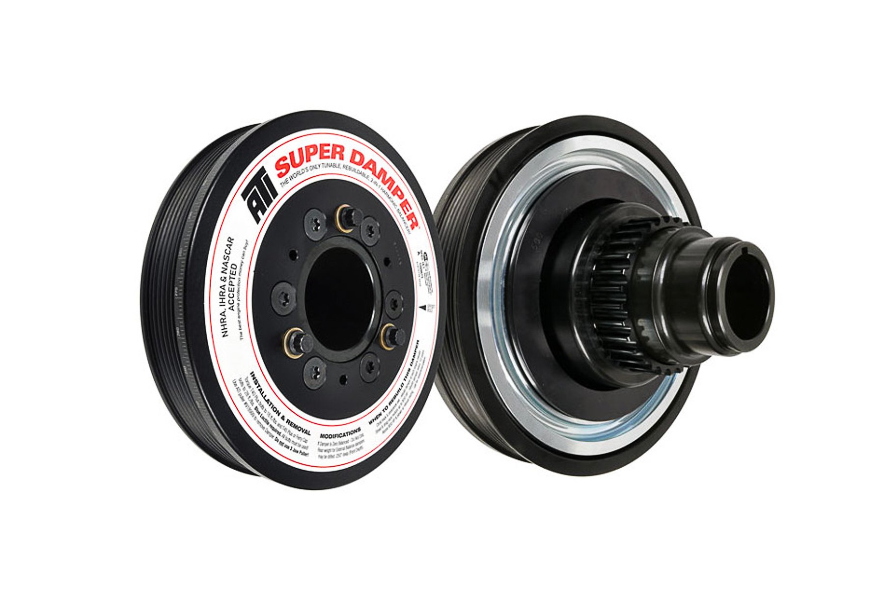
A special hydraulic tool gently forces the damper onto the crank snout. No hammers here!
At this station, the LS9 gets its water pump and harmonic balancer installed. The water pump is bolted in and torqued in place. For the balancer install, Rick uses a special machine that applies hydraulic pressure to the balancer as it attaches it to the crank snout.

Here is the bottom side of the 2.3 Liter Eaton TVS blower. Maximum boost is 10 psi.

An overhead lift helps Rick place the LS9 supercharger onto the engine with precision.
The engine is topped off with its supercharger / manifold unit and top mount intercooler. After the Eaton Gen. VI Twin Vortices Series (TVS) supercharger is bolted into place, the top mount intercooler can be installed. The 2.3L displacement of the Eaton will provide maximum boost of 10.5 psi.

The tube-in-fin intercooler helps lower air inlet temps by up to 140 degrees Fahrenheit.

LS9 Supercharged Script on the intercooler cover lets people know that this engine means business.

Rick Dadd is proud to put his nameplate on each engine he builds. The black tool makes sure it's straight.
After the supercharger unit is installed, the intercooler is mounted on top. The air-to-liquid tube-in-fin intercooler helps lower air inlet temperatures by up to 140 degrees Fahrenheit. The supercharged air comes up and is circulated through the intercooler before entering the intake port. The charge cooler is integrated on a unique manifold system that mounts the “blower” in the engine’s valley, with the charge cooler on top.
After the intercooler is installed, Rick sticks his nameplate on the driver’s side intercooler cover for the whole world to see.

Exhaust plates are installed for engine pressure / leak test.

Air is forced into the oil and water passages and the leak test computer makes sure that there are no leaks.
With the LS9 supercharger in place, the engine is sealed up with exhaust plates and pressure fittings at all fluid inlet / outlet points, and pressure tested. During the timed test, air is forced into the oil and water passages and the leak test computer makes sure that there are no leaks. If pressure isn’t held, the builder has to figure out where the leak is and fix it before the engine can move farther down the line. Builders use a liquid soap substance to detect air leaks – if they see bubbles, there are problems.

All 367 torque settings are kept in a digital file matched to the LS9 engine VIN.
Before the builder can torque down any bolt, he must first scan the appropriate bar code for that set of fasteners. This sets the electronic torque wrench to the proper torque setting and prevents errors. The system won’t let the builder move on to the next set of fasteners until the first ones have been scanned and properly torqued. All of the 367 torque operations are stored on a computer file and are tied to the specific LS9 engine’s serial number. This screen shows the torque settings for each installed part that requires a torque specification.

Green engine lift brackets are installed for use in shipping and installation at Bowling Green.

Exhaust manifolds are installed on the right and left engine banks.
In this series of photos, the exhaust manifolds and green engine lift brackets are installed. The exhaust manifolds are hydroformed stainless steel and are fabricated by a supplier next to the PBC. There is a specific left and right side manifold, and to make sure that there aren’t any mix-ups, the collector studs are installed at separate tables on the right and left side of the engine.
The green engine lift brackets will travel with the engine to Bowling Green, where they will be used to lift the engine during shipping, as well as installation into the car. Once the engine is installed, they are removed and returned to the PBC.

The flywheel is marked for final engine balance at test run cell. Weight will be added to a specific hole based on the computer readout.
The flywheel is marked for final engine balance during the engine run test. Metal will be added to the flywheel and damper during the final computerized balance test that is done on the test run stand. The ZR1’s dual disc clutch pack is the final part to be installed on the engine line.

The engine is weighed to determine how much oil needs to be added to system. 531 pounds is impressive.
The last step for Rick is to weigh the engine. Since the LS9 doesn’t have an oil dipstick, the 10.5 quarts of oil is measured by weight before the test run, so it’s important to know what it weighs dry. Our engine was a lightweight, coming in at 531 pounds.

The engine is first dry run, so it can be externally balanced at damper and flywheel. Then a 45-minute cold test run is performed.
After the weight is recorded, the engine is moved to the test cell area of the building for a test run and balancing. It’s first run by natural gas so it can be externally balanced. Then it’s hooked up to a DC motor and put through a cold test for 45 minutes. After everything checks out, it’s placed on a shipping pallet and is ready for its trip to Bowling Green for installation on the assembly line. According to plant manager Jeff Stafford, in the past year and a half, Bowling Green has never sent back a faulty engine. The cold test cells play a big role in the quality checks before shipping.
If you can’t afford the six-figure ZR1 but have been lusting after the LS9 for your own project, GM Performance Parts offers the LS9 as a fully dressed crate engine. Listed as Part # 19201990, the LS9 comes complete and ready to install for around $23,000.00. In addition to the engine, GM Performance Parts is currently working on an engine wiring harness and Power Control Module (PCM) that will allow the LS9 to run in almost any application.